Assignment 3 Answers
Q3.1
In a 14-bit digitizer, the least significant bit represents $\frac{1}{2^{14}}$ of the full input dynamic range. For small signals (< 5V), the AD dynamic range is 5 V, and the smallest resolvable voltage step is about .3 mV.
Q3.2
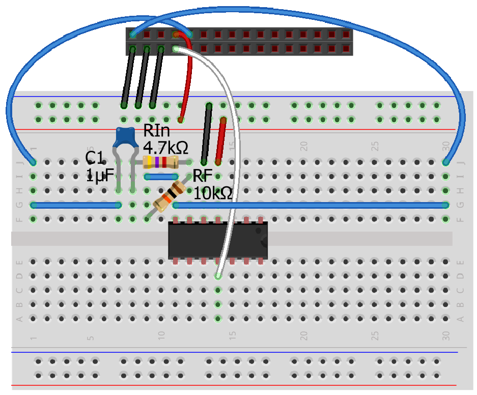
I set up the circuit as follows.
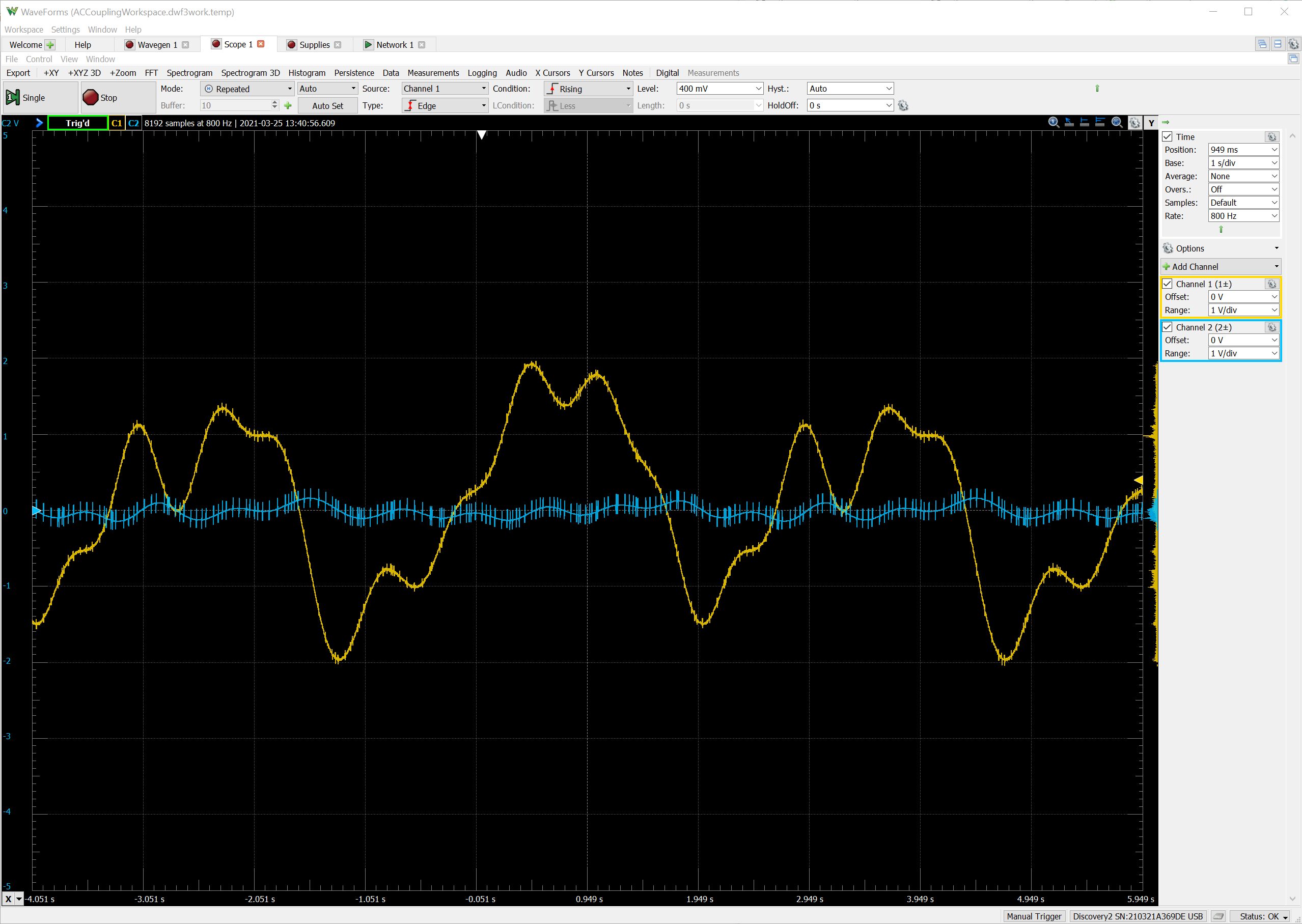
AC coupling significantly attenuates the slowly varying drift while passing through the high-frequency spikes. However, the drift is not completely removed because the blocking capacitor passes through a small fraction of the slow waveform. Furthermore, the amplifier has -2x gain, which amplifies the small spikes.
Q3.3
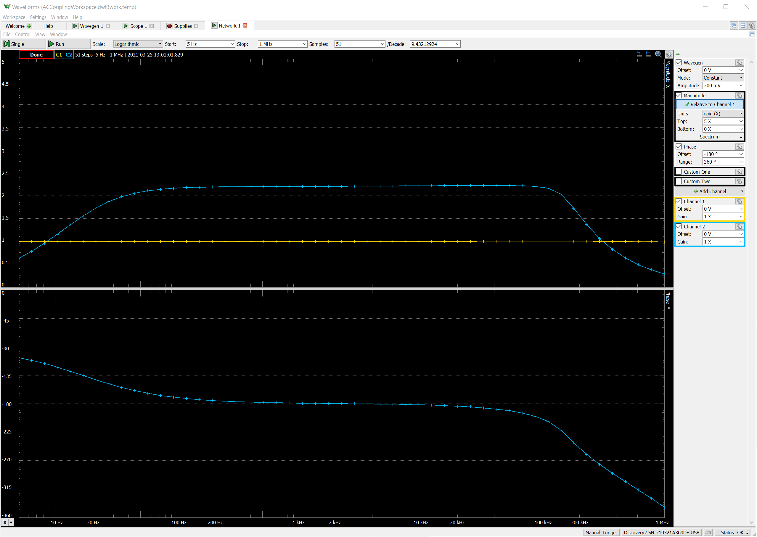
The top half of the Bode Plot shows the magnitude response of the circuit. The gain scale ranges from 0 to 5, and from about 100 Hz to 100 kHz the circuit gain is flat at -2.2. The negative sign can’t be inferred from the magnitude plot alone, but we know that we built an inverting amplifier topology. Furthermore, we can see from the phase plot that between 100 Hz and 100 kHz, the output phase is -180 degrees relative to the input.
Q3.4
(a) As the frequency increases from 1 kHz to 5 kHz, the acquired signal has the correct frequency, though quality of the sine wave degrades around 3–5 kHz. Between 6-10 kHz, the frequency of the acquired signal “folds” around 5 kHz (the Nyquist frequency), with 6 kHz aliasing as 4 kHz, and 7 kHz aliasing as 3 kHz, etc. Between 11–15 kHz, the frequencies “fold” again, around 0 Hz, aliasing as 1–5 kHz.
In all cases, the quality (and amplitude) of the acquired sine wave decreases for aliased frequencies around 5 kHz. This is because it’s difficult to represent a ~5 kHz sine wave with 10 kHz sampling.
(b) Yes, aliasing will occur at 1001 kHz and even higher. In theory it will occur at all higher frequencies, though high frequency noise will trail off in any real system.
Q3.5
We should low-pass filter with a cutoff well below 5 kHz. As we saw, anything above 5 kHz will be aliased, and even frequencies between 3 kHz and 5 kHz could be distorted, so we should attenuate them all before digitizing.
Q3.6
I built a low-pass RC filter with C = 0.1µF and R = 1 kΩ. This should have a 1.6 kHz cutoff frequency.
For my filter, a 1 kHz sine wave is attenuated ~20%. As the frequency increases to 5 kHz, attenuation is greater than 50%. And for frequencies above 15 kHz, attenuation is 90% or more. Thus this does a pretty good job of removing most of the aliasing frequencies while maintaining full signal strength between 0–1 kHz.
Q3.7
The software controlled pulse lasts 101 ms on average with a range of 99.5 – 104.5 ms. (Note, these measurements may differ between computer setups.)
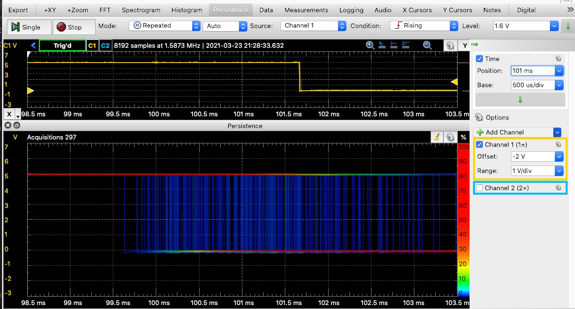
I used the Persistence tab to overlap repeated pulse presentations.
Q3.8
The hardware controlled pulse on W2 is delayed by 0.2 µs from the onset of the pulse on W1. This means that it only takes that long for the hardware to detect the trigger and initiate the pulse waveform.
The hardware controlled pulse lasts 100 ms and shows no jitter (to within the accuracy of the oscilloscope).
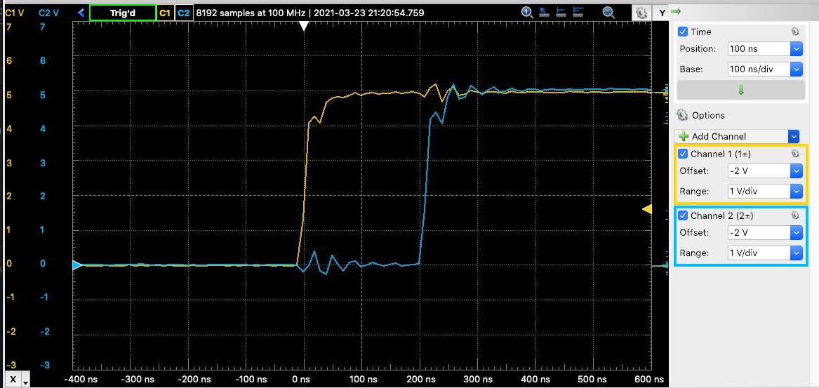
Yellow: software pulse. Blue: hardware pulse.